POWER AMPLIFIERS
Audio amplifiers operate either in a BTL (bridged) or
single-ended (“normal”) configuration. In the single-ended setup, the
output lead goes to the “hot” or “+” side of the load (speaker or
speaker box since we are talking audio) and the “-” or “negative” side
of the load is tied to a common ground shared with the amplifier. In
the BTL configuration, one amp is connected to the “+” side of the
speaker (load) and a second amp is connected to the “-” side of the
load. For this to work, the output signal from the second amplifier
must be a “mirror image” (identical in every respect, but 180 degrees
out of phase) of the output from the first amp. The BTL configuration
is most often seen in low-voltage, battery-powered applications (like
cell phones or “walkman” type personal tape or cd players etc) or in
automotive applications over about 10 watts per channel.
In the BTL configuration, each amp drives half the load impedance.
With the signals being out of phase, the voltage swing across the
load appears to be doubled, and with each amp driving half the
impedance the current is doubled. In theory the bridged pair will
produce 4 times the power into the load that either amp acting alone
could provide. In reality it seldom works that well.
This is an power amplifier circuit of a BTL system, which
comprises a first op-amp chip which outputs an output signal having a
same phase as an input signal input to a signal input terminal, a
second operational amplifier which outputs an output signal having an
opposite phase to the input signal, a voltage divider which generates a
midpoint voltage of the input signal, a first resistor connected
between an output terminal and a negative phase input terminal of the
first operational amplifier, second and third resistors connected in
series between the negative phase input terminals of the first and
second operational amplifiers, a fourth resistor connected between an
output terminal and the negative phase input terminal of the second
operational amplifier, and an impedance converter connected between a
midpoint voltage node of the voltage divider and a series-connection
node of the second and third resistors. (end of abstract)
Gambar Rangkaian Power Amplifier BTL

List Componet:
R1, R2,R3, R4, R6………………… 10kOhm.
R3……………………………………… 20kOhm.
C1, C2, C3, C4……………………… 10µF.
Catu daya (VCC) ±12 V.
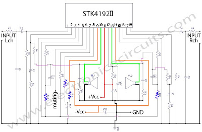
STK 4192 Power Amplifier Circuit Features

according to experience, you have to do a little experiment for you to get the best bass sound, stalwart, gigantic. To get the best bass sound between the subwoofer and the room you, then you should get a ‘pass that point. the following manner:
- The STK4102II series (STK4192II) and STK4101V series (high-grade type) are pin-compatible in the output
- range of 6W to 50W and enable easy design. Small-sized package whose pin assignment is the same
- as that of the STK4101II series
- Built-in muting circuit to cut off various kinds of pop noise
- Greatly reduced heat sink due to substrate temperature 125°C guaranteed
- Excellent cost performance
Layout STK 4192 Power Amplifier

Skema Rangkaian STK 4192 Power Amplifier 50 Watt Stereo

Component ListR1___________ 56K? 1/4W Resistor
R2___________ 56K? 1/4W Resistor
R3___________ 1K? 1/4W Resistor
R4___________ 1K? 1/4W Resistor
R5___________ 560? 1/4W Resistor
R6___________ 560? 1/4W Resistor
R7___________ 100? 1/4W Resistor
R8___________ 100? 1/4W Resistor
R9___________ 56K? 1/4W Resistor
R10__________56K? 1/4W Resistor
R11__________3.3K? 1/4W Resistor
R12__________3.3K? 1/4W Resistor
R13__________3.3K? 1/2W Resistor
R14__________3.3K? 1/2W Resistor
R15__________4.7? 1/4W Resistor
R16__________4.7? 1/4W Resistor
R17__________1K? 1/2W Resistor
R18__________1K? 1/4W Resistor C1___________ 400pF Polyester Capacitor
C2___________ 400pF Polyester Capacitor
C3___________ 2.2µF Polyester Capacitor
C4___________ 2.2µF 50V Electrolytic Capacitor
C5___________ 100µF 50V Electrolytic Capacitor
C6___________ 100µF 50V Electrolytic Capacitor
C7___________ 0.1µF 50V Electrolytic Capacitor
C8___________ 0.1µF 50V Electrolytic Capacitor
C9___________ 10µF 50V Electrolytic Capacitor
C10___________ 10µF 50V Electrolytic Capacitor
C11___________ 47µF 50V Electrolytic Capacitor
C12___________ 47µF 50V Electrolytic Capacitor
C13___________ 100µF 50V Electrolytic Capacitor
C14___________ 10µF 50V Electrolytic Capacitor
IC___________ STK4192II Integrated STK Power Amplifier series

power sapply recommend for the STK 4192
Tips that bass sound more feltaccording to experience, you have to do a little experiment for you to get the best bass sound, stalwart, gigantic. To get the best bass sound between the subwoofer and the room you, then you should get a ‘pass that point. the following manner:
- Place the subwoofer on your location on our seat. (sub Woofer do not be put on the table / cupboard you high more than 1 / 2 meter)
- Turn the sub Woofer and you do not forget to disconnect the speaker Amplifier.
- Play a song you like, which have gained a good frequency bass
- Then try running memutari room, see the characters that appear bass.
- You will hear some of the bass sound quality improvements in some corner of the room. This happens due to the interaction between low-frequency space and you. Nah corners you can select as a “node” or the point pas you need to immediately place your subwoofer in a corner of it.
There are some important updates to this project, as shown below.
Recent testing has shown that with the new ON Semi transistors it is
possible to obtain a lot more power than previously. The original
design was very conservative, and was initially intended to use
2SA1492 and 2SC3856 transistors (rated at 130W) – with 200W (or 230W)
devices, some of the original comments and warnings have been amended
to suit.
Note:- This amplifier is not trivial, despite its small size and apparent simplicity. The total DC is over 110V (or as much as 140V DC!), and can kill you.
- The power dissipated is such that great care is needed with transistor mounting.
- The single board P68 is capable of full power duty into 4 Ohm loads, but only at the lower supply voltage.
- For operation at the higher supply voltage, you must use the dual board version.
- There is NO SHORT CIRCUIT PROTECTION. The amp is designed to be used within a subwoofer or other speaker enclosure, so this has not been included. A short on the output will destroy the amplifier.
Continuous power into 8 ohms is typically over 150W (250W for ±70V supplies), and it can be used without additional transistors at full power into an 8 ohm load all day, every day. The additional transistors are only needed if you want to do the same thing into 4 ohms at maximum supply voltage! Do not even think about using supplies over ±70V, and don’t bother asking me if it is ok – it isn.
This is a circuit of 1000watt power amplifier.
This time I don’t have a picture to the circuit board, but because
the amplifier circuit is quite simple, you can design it yourself PCB
easily or you can order it at the store PCB audio kit in the center of
electronic singosaren oriental, solo.

Skema Rangkaian Sanken 1000 watt
The assemble cables for DC power supply and output transistors
must be large, use size 1.5-3mm for large current passed. The supply
used transformer with 20A/45Ct and at least 4×10000uf/80 volt
capasitor. this circuit is able to supply power 10000watt therefore the
power transistor will be very hot, give good cooling fan on the power
transisitor
Transitor alternative to replacement of the 2SA1494 is 2SA1216 From SANKEN. The transistor has a 200-350 watt power dissipation of each pair so that for long-term operation of more durable. Keep in mind, usually sold a pair of power transistors with its complement, so you can not buy 2SC2922 alone without 2SA1216 or 2SA1494 without 2SC3858. The price range for transitor tsb is 30-40 thousand Rupiah / pair.
Transitor alternative to replacement of the 2SA1494 is 2SA1216 From SANKEN. The transistor has a 200-350 watt power dissipation of each pair so that for long-term operation of more durable. Keep in mind, usually sold a pair of power transistors with its complement, so you can not buy 2SC2922 alone without 2SA1216 or 2SA1494 without 2SC3858. The price range for transitor tsb is 30-40 thousand Rupiah / pair.
When I began the design of this amp, my goal was to make a
product better suited for the reproduction of complex music and voice.
Although I emphasize the high electrical properties, the most
important requirement is to create a superior sound, vivid images and
superb spatial aural clarity.Although the average level of listening
is usually less than 10 watts, my design concept was to an amplifier
with plenty of reserves, but the deviation is for Class A, at the
height of the audience of cross-over distortion at a very low level.
There is no place in the pathway, enhances the precision of the tonal
characteristics of instruments and voices clearly. This Amplifier is
virtually zero phase distortion over the audio range resolution is
perfect and completely color the sound.

Skema Rangkaian Power Amplifier MJ15003 -MJ15004
Amplifier Specification:Maximum Output: 240 watts rms into 8 Ohms, 380 watts rms into 4 Ohms
Audio Frequency Linearity: 20 Hz – 20 kHz (+0, -0.2 dB)
Closed Loop Gain: 32 dB
Hum and Noise: -90 dB (input short circuit)
Output Offset Voltage: >13 mV (input short circuit)
Phase Linearity: > 13 0 (10 Hz – 20 kHz)
Harmonic Distortion: > 0.007% at rated power
IM Distortion: > .009% at maximum power
2000Watt Power Amplifier
Thursday, April 8th, 2010
This power amplifier circuit provides up to 2000Watt, it has to
be said that this amplifier will blow up any speaker connected to it.
I recommend this as a ‘thought experiment’, rather than actually
doing it!. 110V RMS into 8 ohms is 1500 W. How long would you expect
the speaker to last? Most will be toast within perhaps 30 seconds or
less!
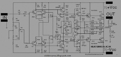
 Skema rangkian power amplifier sound system 2000 watt
The transistor Q5 (the bias servo transistor) is mounted on the
heatsink, in excellent thermal contact. This is because, unlike most of
my other designs, this amp uses conventional Darlington output
configuration. It is necessary to use a Darlington arrangement (or a
low power Darlington transistor as shown) for Q5 to ensure that the
bias remains at a safe value with temperature. There is probably good
cause to model and test this aspect of the design very carefully,
because it is so important. The arrangement as shown will reduce
quiescent current at elevated temperatures. For example, if total Iq at
24°C is 165mA, this will fall to ~40mA at 70°C. This is probably
fine, because there is some delay between the a power ’surge’ and the
output transistors transferring their heat to the bias servo via the
heatsink.
The power supply needed for an amp of this size is massive. Grown
welding machines will look at it and cry. For intermittent operation,
you need a minimum of a 1000VA transformer (or 1500VA for the 2000W
version), and it will have to be custom made because of the voltages
used. If you expect to run the amp at continuous high power, then
transformers should be 2kVA and 3000VA respectively. Filter capacitors
will pose a problem – because you need caps rated for 150V, these will
be hard to find. Because high voltage high value caps can be
difficult to find, it may be necessary to use two electros in series
for each capacitor location. This is the arrangement shown. You must
include the resistors in parallel – these equalise the voltage across
each capacitor so that they have the same voltage. Remember to verify
the ripple current rating! This can be expected to be over 10A, and
under-rated capacitors will blow up.
Skema Rangkian Power Supplay 2000 VA
WARNINGThis project describes an amplifier, power supply and tests procedures that are all inherently dangerous. Nothing described in this article should even be considered unless you are fully experienced, know exactly what you are doing, and are willing to take full 100% responsibility for what you do. There are aspects of the design that may require analysis, fault-finding and/or modification
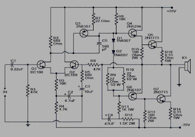
This is the circuit of subwoofer amplifier. This amplifier can
produce an output of 100Watt. There are seven transistors including
four in the output stage. The transistors Q1 and Q2 form the
preamplifier stage. Transistors Q4 to Q7 form the output stage. Since
no ICs are used the circuit is very robust and can be easily assembled
on a general purpose PCB.
Note:Use powered a +35V/-35V, 5A dual power supply.
All electrolytic capacitors must be rated 100V.
The transistor Q4 to Q7 must be fitted with heat sinks.
Transistor 2N3773 and 2N6609
Transistor 2N3773 (NPN) and (PNP) 2N6609 are PowerBase_ power transistors designed for high power audio, disk head positioners and other linear applications. These devices can also be used in power switching circuits such as relay or solenoid drivers, DC?DC converters or inverters.

Features Transistor 2N3773
Pb?Free Packages are Available
High Safe Operating Area (100% Tested) 150 W @ 100 V
Completely Characterized for Linear Operation
High DC Current Gain and Low Saturation Voltage
hFE = 15 (Min) @ 8.0 A, 4.0 V
VCE(sat) = 1.4 V (Max) @ IC = 8.0 A, IB = 0.8 A
For Low Distortion Complementary Designs
MAXIMUM RATINGS Transistor 2N3773
Collector ? Emitter Voltage: 140 Vdc
Collector ? Emitter Voltage: 160 Vdc
Collector ? Base Voltage:160 Vdc
Emitter ? Base Voltage: 7 Vdc
Collector Current Continuous: 16 Adc
Base Current Continuous 15 Adc
Total Power Dissipation : 150 Watt.
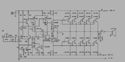
Amplifier 300 Watt
Jul 2003 OnSemi released a new range of transistors, designed
specifically for audio applications. These new transistors have been
tested in the P68, and give excellent results. As a result, all
previous recommendations for output transistors are superseded, and
the new transistors should be used.
The transistors are MJL4281A (NPN) and MJL4302A (PNP), and feature
high bandwidth, excellent safe operating area, high linearity and
high gain. Driver transistors are MJE15034 (NPN) and MJE15035 (PNP).
All devices are rated at 350V, with the power transistors having a
230W dissipation and the drivers are 50W.
- The total DC is over 110V and can kill you.
- The power dissipated is such that great care is needed with transistor mounting..
- The amplifier circuit is NO SHORT CIRCUIT PROTECTION. The amp is designed to be used within a subwoofer or other speaker enclosure, so this has not been included. A short on the output will destroy the amplifier.
- Transistor MJL4281A and MJL4302A are new most constructors will find that these are not as easy to get as they should be. The alternatives are MJL3281/ MJL1302 or MJL21193/ MJL21194.
If you are fanatical about the use of transistors jengkol 2N3055
and MJ2955 then this circuit is the answer. This OCL power amplifier
circuit deliver a blasting 150 watt to a 4 Ohm speaker. The amplifier
circuit is very cheapest and can be powered from 24 to 32 V/5A dual
power supply. You must try this circuit. Its working great. Because
Transisitor on the final amplifier will be very hot then add the
aluminum finned cooler and the fan so that the transistor is not too
high temperatures
The transistor 2N3055 NPN and MJ2955 PNP are a silicon
Epitaxial-Base Planar transistor mounted in Jedec TO-3 metal case. It
is intended for power switching circuits, series and shunt regulators,
output stages and high fidelity amplifiers.
Skema Rangkaian 150 Watt OCL
- Use a well regulated and filtered power supply.
- Connect a 50K POT in series with the input as volume control if you need.Not shown in circuit diagram

maximum rating Transistor 2N3055 NPN and MJ2955 PNP
- Collector-Base Voltage : 100 V
- Collector-Emitter Voltage: 70 V
- Collector-Emitter Voltage: 60 V
- VEBO Emitter-Base Voltage: 7 V
- IC Collector Current: 15 A
- IB Base Current: 7 A
- Total Dissipation: 115 W
- Storage Temperature: -65 to 200 oC
- Tj Max. Operating Junction Temperature 200 oC
| LM386 0,325W Audio Amplifier The LM386 is a power amplifier designed for use in low voltage consumer applications. The gain is internally set to 20 to keep external part count low, but the addition of an external resistor and capacitor between pins 1 and 8 will increase the gain to any value from 20 to 200.
The inputs are ground referenced while the output automatically
biases to one-half the supply voltage. The quiescent power drain is only
24 milliwatts when operating from a 6 volt supply, making the LM386
ideal for battery operation. Features n Battery operation n Minimum
external parts n Wide supply voltage range: 4V–12V or 5V–18V n Low
quiescent current drain: 4mA n Voltage gains from 20 to 200 n Ground
referenced input n Self-centering output quiescent voltage n Low
distortion: 0.2% (AV = 20, VS = 6V, RL = 8W, PO = 125mW, f = 1kHz) n
Available in 8 pin MSOP package
|


thank vry mch for administrator, speas for 2000 watt aplifier
BalasHapusokyyy
BalasHapus