Selasa, 05 Juni 2012

POWER AMPLIEIERS

POWER AMPLIFIERS


Audio amplifiers operate either in a BTL (bridged) or single-ended (“normal”) configuration. In the single-ended setup, the output lead goes to the “hot” or “+” side of the load (speaker or speaker box since we are talking audio) and the “-” or “negative” side of the load is tied to a common ground shared with the amplifier. In the BTL configuration, one amp is connected to the “+” side of the speaker (load) and a second amp is connected to the “-” side of the load. For this to work, the output signal from the second amplifier must be a “mirror image” (identical in every respect, but 180 degrees out of phase) of the output from the first amp. The BTL configuration is most often seen in low-voltage, battery-powered applications (like cell phones or “walkman” type personal tape or cd players etc) or in automotive applications over about 10 watts per channel.
In the BTL configuration, each amp drives half the load impedance. With the signals being out of phase, the voltage swing across the load appears to be doubled, and with each amp driving half the impedance the current is doubled. In theory the bridged pair will produce 4 times the power into the load that either amp acting alone could provide. In reality it seldom works that well.
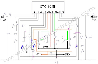
This is an power amplifier circuit of a BTL system, which comprises a first op-amp chip which outputs an output signal having a same phase as an input signal input to a signal input terminal, a second operational amplifier which outputs an output signal having an opposite phase to the input signal, a voltage divider which generates a midpoint voltage of the input signal, a first resistor connected between an output terminal and a negative phase input terminal of the first operational amplifier, second and third resistors connected in series between the negative phase input terminals of the first and second operational amplifiers, a fourth resistor connected between an output terminal and the negative phase input terminal of the second operational amplifier, and an impedance converter connected between a midpoint voltage node of the voltage divider and a series-connection node of the second and third resistors. (end of abstract)
Power Amplifier BTL

Power Amplifier BTL
List Componet:
R1, R2,R3, R4, R6………………… 10kOhm.
R3……………………………………… 20kOhm.
C1, C2, C3, C4……………………… 10µF.
Catu daya (VCC) ±12 V.

STK 4192 Power Amplifier Circuit Features

STK 4192 Power Amplifier Circuit Features
  • The STK4102II series (STK4192II) and STK4101V series (high-grade type) are pin-compatible in the output
  • range of 6W to 50W and enable easy design. Small-sized package whose pin assignment is the same
  • as that of the STK4101II series
  • Built-in muting circuit to cut off various kinds of pop noise
  • Greatly reduced heat sink due to substrate temperature 125°C guaranteed
  • Excellent cost performance
Rangkaian STK 4192 Power Amplifier 50 Watt Stereo

Layout STK 4192 Power Amplifier
Rangkaian STK 4192 Power Amplifier 50 Watt Stereo
Skema Rangkaian STK 4192 Power Amplifier 50 Watt Stereo
Component ListR1___________ 56K? 1/4W Resistor
R2___________ 56K? 1/4W Resistor
R3___________ 1K? 1/4W Resistor
R4___________ 1K? 1/4W Resistor
R5___________ 560? 1/4W Resistor
R6___________ 560? 1/4W Resistor
R7___________ 100? 1/4W Resistor
R8___________ 100? 1/4W Resistor
R9___________ 56K? 1/4W Resistor
R10__________56K? 1/4W Resistor
R11__________3.3K? 1/4W Resistor
R12__________3.3K? 1/4W Resistor
R13__________3.3K? 1/2W Resistor
R14__________3.3K? 1/2W Resistor
R15__________4.7? 1/4W Resistor
R16__________4.7? 1/4W Resistor
R17__________1K? 1/2W Resistor
R18__________1K? 1/4W Resistor C1___________ 400pF Polyester Capacitor
C2___________ 400pF Polyester Capacitor
C3___________ 2.2µF Polyester Capacitor
C4___________ 2.2µF 50V Electrolytic Capacitor
C5___________ 100µF 50V Electrolytic Capacitor
C6___________ 100µF 50V Electrolytic Capacitor
C7___________ 0.1µF 50V Electrolytic Capacitor
C8___________ 0.1µF 50V Electrolytic Capacitor
C9___________ 10µF 50V Electrolytic Capacitor
C10___________ 10µF 50V Electrolytic Capacitor
C11___________ 47µF 50V Electrolytic Capacitor
C12___________ 47µF 50V Electrolytic Capacitor
C13___________ 100µF 50V Electrolytic Capacitor
C14___________ 10µF 50V Electrolytic Capacitor
IC___________ STK4192II Integrated STK Power Amplifier series
power sapply recommend for the STK 4192
Tips that bass sound more felt
according to experience, you have to do a little experiment for you to get the best bass sound, stalwart, gigantic. To get the best bass sound between the subwoofer and the room you, then you should get a ‘pass that point. the following manner:
  1. Place the subwoofer on your location on our seat. (sub Woofer do not be put on the table / cupboard you high more than 1 / 2 meter)
  2. Turn the sub Woofer and you do not forget to disconnect the speaker Amplifier.
  3. Play a song you like, which have gained a good frequency bass
  4. Then try running memutari room, see the characters that appear bass.
  5. You will hear some of the bass sound quality improvements in some corner of the room. This happens due to the interaction between low-frequency space and you. Nah corners you can select as a “node” or the point pas you need to immediately place your subwoofer in a corner of it.

500Watt Power Amplifier

There are some important updates to this project, as shown below. Recent testing has shown that with the new ON Semi transistors it is possible to obtain a lot more power than previously. The original design was very conservative, and was initially intended to use 2SA1492 and 2SC3856 transistors (rated at 130W) – with 200W (or 230W) devices, some of the original comments and warnings have been amended to suit.
Rangkaian 500Watt Power Amplifier Skema Rangkaian 500Watt
 Power Amplifier
Note:
  • This amplifier is not trivial, despite its small size and apparent simplicity. The total DC is over 110V (or as much as 140V DC!), and can kill you.
  • The power dissipated is such that great care is needed with transistor mounting.
  • The single board P68 is capable of full power duty into 4 Ohm loads, but only at the lower supply voltage.
  • For operation at the higher supply voltage, you must use the dual board version.
  • There is NO SHORT CIRCUIT PROTECTION. The amp is designed to be used within a subwoofer or other speaker enclosure, so this has not been included. A short on the output will destroy the amplifier.
Please note that the specification for this amp has been upgraded, and it is now recommended for continuous high power into 4 Ohms, but You will need to go to extremes with the heatsink (fan cooling is highly recommended). It was originally intended for “light” intermittent duty, suitable for an equalised subwoofer system (for example using the ELF principle – see the Project Page for the info on this circuit). Where continuous high power is required, another 4 output transistors are recommended, wired in the same way as Q9, Q10, Q11 and Q12, and using 0.33 ohm emitter resistors.
Continuous power into 8 ohms is typically over 150W (250W for ±70V supplies), and it can be used without additional transistors at full power into an 8 ohm load all day, every day. The additional transistors are only needed if you want to do the same thing into 4 ohms at maximum supply voltage! Do not even think about using supplies over ±70V, and don’t bother asking me if it is ok – it isn.

1000Watt Power Amplifier

This is a circuit of 1000watt power amplifier. This time I don’t have a picture to the circuit board, but because the amplifier circuit is quite simple, you can design it yourself PCB easily or you can order it at the store PCB audio kit in the center of electronic singosaren oriental, solo.amplifier 1000 watt
Skema Rangkaian Sanken 1000 watt


Power Amplifier MJ15003 -MJ15004

When I began the design of this amp, my goal was to make a product better suited for the reproduction of complex music and voice. Although I emphasize the high electrical properties, the most important requirement is to create a superior sound, vivid images and superb spatial aural clarity.Although the average level of listening is usually less than 10 watts, my design concept was to an amplifier with plenty of reserves, but the deviation is for Class A, at the height of the audience of cross-over distortion at a very low level. There is no place in the pathway, enhances the precision of the tonal characteristics of instruments and voices clearly. This Amplifier is virtually zero phase distortion over the audio range resolution is perfect and completely color the sound.
Rangkain Power Amplifier MJ15003 -MJ15004
Skema Rangkaian Power Amplifier MJ15003 -MJ15004
Amplifier Specification:
Maximum Output: 240 watts rms into 8 Ohms, 380 watts rms into 4 Ohms
Audio Frequency Linearity: 20 Hz – 20 kHz (+0, -0.2 dB)
Closed Loop Gain: 32 dB
Hum and Noise: -90 dB (input short circuit)
Output Offset Voltage: >13 mV (input short circuit)
Phase Linearity: > 13 0 (10 Hz – 20 kHz)
Harmonic Distortion: > 0.007% at rated power
IM Distortion: > .009% at maximum power

2000Watt Power Amplifier

Thursday, April 8th, 2010
This power amplifier circuit provides up to 2000Watt, it has to be said that this amplifier will blow up any speaker connected to it. I recommend this as a ‘thought experiment’, rather than actually doing it!. 110V RMS into 8 ohms is 1500 W. How long would you expect the speaker to last? Most will be toast within perhaps 30 seconds or less!
Rangkian Power Amplifier 2000 WattSkema rangkian power amplifier sound system 2000 watt
The transistor Q5 (the bias servo transistor) is mounted on the heatsink, in excellent thermal contact. This is because, unlike most of my other designs, this amp uses conventional Darlington output configuration. It is necessary to use a Darlington arrangement (or a low power Darlington transistor as shown) for Q5 to ensure that the bias remains at a safe value with temperature. There is probably good cause to model and test this aspect of the design very carefully, because it is so important. The arrangement as shown will reduce quiescent current at elevated temperatures. For example, if total Iq at 24°C is 165mA, this will fall to ~40mA at 70°C. This is probably fine, because there is some delay between the a power ’surge’ and the output transistors transferring their heat to the bias servo via the heatsink.
The power supply needed for an amp of this size is massive. Grown welding machines will look at it and cry. For intermittent operation, you need a minimum of a 1000VA transformer (or 1500VA for the 2000W version), and it will have to be custom made because of the voltages used. If you expect to run the amp at continuous high power, then transformers should be 2kVA and 3000VA respectively. Filter capacitors will pose a problem – because you need caps rated for 150V, these will be hard to find. Because high voltage high value caps can be difficult to find, it may be necessary to use two electros in series for each capacitor location. This is the arrangement shown. You must include the resistors in parallel – these equalise the voltage across each capacitor so that they have the same voltage. Remember to verify the ripple current rating! This can be expected to be over 10A, and under-rated capacitors will blow up.
Skema Rangkian Power Supplay 2000 VA
WARNING
This project describes an amplifier, power supply and tests procedures that are all inherently dangerous. Nothing described in this article should even be considered unless you are fully experienced, know exactly what you are doing, and are willing to take full 100% responsibility for what you do. There are aspects of the design that may require analysis, fault-finding and/or modification

Rangkaian 100 watt sub woofer

This is the circuit of subwoofer amplifier. This amplifier can produce an output of 100Watt. There are seven transistors including four in the output stage. The transistors Q1 and Q2 form the preamplifier stage. Transistors Q4 to Q7 form the output stage. Since no ICs are used the circuit is very robust and can be easily assembled on a general purpose PCB.
100 watt sub-woofer amplifierSkema rangkaian 100 watt sub-woofer amplifier
Note:
Use powered a +35V/-35V, 5A dual power supply.
All electrolytic capacitors must be rated 100V.
The transistor Q4 to Q7 must be fitted with heat sinks.
Transistor 2N3773 and 2N6609
Transistor 2N3773 (NPN) and (PNP) 2N6609 are PowerBase_ power transistors designed for high power audio, disk head positioners and other linear applications. These devices can also be used in power switching circuits such as relay or solenoid drivers, DC?DC converters or inverters.
Transistor 2N3773
Features Transistor 2N3773
Pb?Free Packages are Available
High Safe Operating Area (100% Tested) 150 W @ 100 V
Completely Characterized for Linear Operation
High DC Current Gain and Low Saturation Voltage
hFE = 15 (Min) @ 8.0 A, 4.0 V
VCE(sat) = 1.4 V (Max) @ IC = 8.0 A, IB = 0.8 A
For Low Distortion Complementary Designs
MAXIMUM RATINGS Transistor 2N3773
Collector ? Emitter Voltage: 140 Vdc
Collector ? Emitter Voltage: 160 Vdc
Collector ? Base Voltage:160 Vdc
Emitter ? Base Voltage: 7 Vdc
Collector Current Continuous: 16 Adc
Base Current Continuous 15 Adc
Total Power Dissipation : 150 Watt.

Amplifier 300 Watt


Jul 2003 OnSemi released a new range of transistors, designed specifically for audio applications. These new transistors have been tested in the P68, and give excellent results. As a result, all previous recommendations for output transistors are superseded, and the new transistors should be used.
The transistors are MJL4281A (NPN) and MJL4302A (PNP), and feature high bandwidth, excellent safe operating area, high linearity and high gain. Driver transistors are MJE15034 (NPN) and MJE15035 (PNP). All devices are rated at 350V, with the power transistors having a 230W dissipation and the drivers are 50W.
Rangkaian Amplifier 300 WattSkema rangkaian amplif 300 watt
Note:
  • The total DC is over 110V and can kill you.
  • The power dissipated is such that great care is needed with transistor mounting..
  • The amplifier circuit is NO SHORT CIRCUIT PROTECTION. The amp is designed to be used within a subwoofer or other speaker enclosure, so this has not been included. A short on the output will destroy the amplifier.
  • Transistor MJL4281A and MJL4302A are new most constructors will find that these are not as easy to get as they should be. The alternatives are MJL3281/ MJL1302 or MJL21193/ MJL21194.
All three driver transistors (Q4, 5 & 6)must be on a heatsink, and D2 and D3 should be in good thermal contact with the driver heatsink. Neglect to do this and the result will be thermal runaway, and the amp will fail. For some reason, the last statement seems to cause some people confusion – look at the photo below, and you will see the small heatsink, 3 driver transistors, and a white “blob” (just to the left of the electrolytic capacitor), which is the two diodes pressed against the heatsink with thermal grease.

150 Watt OCL Power Amplifier

If you are fanatical about the use of transistors jengkol 2N3055 and MJ2955 then this circuit is the answer. This OCL power amplifier circuit deliver a blasting 150 watt to a 4 Ohm speaker. The amplifier circuit is very cheapest and can be powered from 24 to 32 V/5A dual power supply. You must try this circuit. Its working great. Because Transisitor on the final amplifier will be very hot then add the aluminum finned cooler and the fan so that the transistor is not too high temperaturesRangkaian 150 Watt OCL Amplifier
Skema Rangkaian 150 Watt OCL 
  • Use a well regulated and filtered power supply.
  • Connect a 50K POT in series with the input as volume control if you need.Not shown in circuit diagram
The transistor 2N3055 NPN and MJ2955 PNP are a silicon Epitaxial-Base Planar transistor mounted in Jedec TO-3 metal case. It is intended for power switching circuits, series and shunt regulators, output stages and high fidelity amplifiers.

maximum rating Transistor 2N3055 NPN and MJ2955 PNP
  • Collector-Base Voltage : 100 V
  • Collector-Emitter Voltage: 70 V
  • Collector-Emitter Voltage: 60 V
  • VEBO Emitter-Base Voltage: 7 V
  • IC Collector Current: 15 A
  • IB Base Current: 7 A
  • Total Dissipation: 115 W
  • Storage Temperature: -65 to 200 oC
  • Tj Max. Operating Junction Temperature 200 oC

LM386 0,325W Audio Amplifier


LM386 0,325W Audio Amplifier

LM386 0,325W Audio Amplifier

The LM386 is a power amplifier designed for use in low voltage consumer applications. The gain is internally set to 20 to keep external part count low, but the addition of an external resistor and capacitor between pins 1 and 8 will increase the gain to any value from 20 to 200.
The inputs are ground referenced while the output automatically biases to one-half the supply voltage. The quiescent power drain is only 24 milliwatts when operating from a 6 volt supply, making the LM386 ideal for battery operation. Features n Battery operation n Minimum external parts n Wide supply voltage range: 4V–12V or 5V–18V n Low quiescent current drain: 4mA n Voltage gains from 20 to 200 n Ground referenced input n Self-centering output quiescent voltage n Low distortion: 0.2% (AV = 20, VS = 6V, RL = 8W, PO = 125mW, f = 1kHz) n Available in 8 pin MSOP package

Sabtu, 19 Mei 2012

Proteksi Panasonik Sanyo LG Sharp Politron dan Parameter Sharf Wonder

protexi panasonic


Masukan Proteksi Detektor Yang Dideteksi Tegangan Normal Menonaktifkan Proteksi
Pin No.20 IC601 (0 Volt) R428 (56K) Vertikal Output R428 = 0 Volt Lepaskan R428
D522 Heater / X-ray Anoda D522 = 0 Volt Lepaskan D522
Q451 Tegangan 24V Collector Q451 = 0 Volt Lepaskan Q451
Q503 Tegangan 12V. Collector Q503 = 0 Volt Lepaskan Q503
Pin No.50 IC1102 (5.3 Volt) Q1136 Sinkronisasi Video Pin No.50 IC1102 = 5.3 Volt Lepaskan Q1136
Panasonic MN152810TTD6, AN5607K
Masukan Proteksi Detektor Yang Dideteksi Tegangan Normal Menonaktifkan Proteksi
Pin No.20 IC601 (0 Volt) R474 (47K) Vertikal Output R474 = 0 Volt Lepaskan R474
Q451 Tegangan 24V Collector Q451 = 0 Volt Lepaskan Q451
Q503 Tegangan 12V Collector Q503 = 0 Volt Lepaskan Q503
Pin No.50 IC1102 (5.3 volt) Q1136 Sinkronisasi Video Pin No.50 IC1102 = 5.3 Volt Lepaskan Q1136
Panasonic GOLD Series, MN1528111, AN5192K-A
Masukan Proteksi Detektor Yang Dideteksi Tegangan Normal Menonaktifkan Proteksi
Pin No.55 IC601 (0 Volt) D544 (MA410B) X-ray Anoda D544 = 0 Volt Lepaskan D544
R426 (56K) Vertikal Output R426 = 0 Volt Lepaskan R426
Q503 (A564) Tegangan 12V Collector Q503 = 0 Volt Lepaskan Q503
Q451 (A564) Tegangan 24V Collector Q451 = 0 Volt Lepaskan Q451
Panasonic MX-5A Chassis, MN1871681TFK, M52770ASP
Masukan Proteksi Detektor Yang Dideteksi Tegangan Normal Menonaktifkan Proteksi
Pin No.36 IC601 (0 Volt) D590 (MA4108) X-ray Anoda D590 = 0 Volt Lepaskan D590
Q580 (B709) Tegangan 24V Collector Q580 = 0 Volt Lepaskan Q580
Q581 (B709) Tegangan 9V Collector Q581 = 0 Volt Lepaskan Q581


protexi SANYO


Model / Series Masukan Proteksi Detektor Yang Dideteksi Menonaktifkan Proteksi
Chasis FC-3A Pin No.27 IC Micom
(LC 8634XX / LC 8632XX, QXXAVB864P, QXXAVC044P)
Me-nonaktifkan protek utama,
lepaskan R830 (1 K ohm) Q527 Vertical Lepaskan RQ527
D681 Tegangan 9V Lepaskan D681
D682 Tegangan 24V Lepaskan D682
Q449, D468 X-Ray Lepaskan Q449 & D468
D664 Tegangan 12V Lepaskan D664
D486 Tegangan 180V Lepaskan D486
Chasis EB-2A, AA1-A Pin No.31 IC Micom (QXXAAC22XX) D392 Tegangan 24V Lepaskan D392
D393 Tegangan 12V Lepaskan D393
D391 Tegangan 180V Lepaskan D391
Chasis AC-1A Pin No.41 IC Micom (QXXAAC23XX) D445 ABL/X-Ray Lepaskan D445
D492 Tegangan 180V Lepaskan D492
D655 Tegangan 8V Lepaskan D655
D654 Tegangan 12V Lepaskan D654
Q527 Vertikal Out Lepaskan Q527
D646 Tegangan 24V Lepaskan D646
Chasis A-3A Pin No.15 IC Micom (M34300N4-XXXSP) D792 Tegangan 9V Lepaskan D792
CG21XS2 Pin No.23 IC Jungle (LA769XX) Power fail Lepaskan J830

tv sanyo 3detik stanby
Coba lepas dzener sensor EHT yang terhubung dengan heater

protexi sony


Model / Series Masukan Proteksi Menonaktifkan Pusat Proteksi Detektor Yang Dideteksi Menonaktifkan Proteksi
Chasis BG-2T Pin No.50 IC 301(TDA8844) = 1.5V Lepaskan R368 (1KΩ) R369 (1.2MΩ) ABL Lepaskan R369
D501 X-Ray Lepaskan D501
Chasis BG-2S Pin No.50 IC 01(TDA8374) = 1.5V Lepaskan R341 (1KΩ) D1505 Vertikal Lepaskan D1505
R319 (1.2MΩ) ABL Lepaskan R319
D591 X-Ray Lepaskan D591
Chasis BG-2 Pin No.48 IC 01(TDA8366) = 1.5V Lepaskan R341 (1KΩ) D1505 Vertikal Lepaskan D1505
R319 (1.2MΩ) ABL Lepaskan R319
D591 X-Ray Lepaskan D591

protexi LG


Model / Series Masukan Proteksi Menonaktifkan Pusat Proteksi Detektor Yang Dideteksi Menonaktifkan Proteksi
Chasis MC-83A Pin No.8 IC 01(M37272M) = 4V Lepaskan Q16 (C3198Y) D401 Heater / X-Ray Lepaskan D401
D402 Tegangan 115V Lepaskan D402
Chasis MC-84A Pin No.41 IC 01(CXP86324) = 3.8V Lepaskan R57 (100 Ω) D301 Tegangan 16V Lepaskan D301
D303 Tegangan 45V Lepaskan D303
D744 Heater / X-Ray Lepaskan D744
Chasis MC-64A Pin No.20 IC 01(LG8634-15D) = 5V Lepaskan JP102 Q302 Vertikal Output Lepaskan Q302
D408 Tegangan pada T402 Lepaskan D408
D415 Tegangan 8V Lepaskan D415
D8002 Heater / X-Ray Lepaskan D8002
D416 Tegangan 8V Lepaskan D416
Chasis MC-059 Pin No.25 IC 501(LG631) = 5V Lepaskan Q16(C103) Q403 Tegangan 110V Lepaskan R423 (12K)
D303 Vertikal Lepaskan D303
D401 Heater / X-Ray Lepaskan D401


protexi sharp


. Protektor input pin-7 - normal tegangan “high”
2. AC det input pin-6 - normal tegangan “high”
3. AC 50/60 input pin-15– normal tegangan “high”


1. Protektor input pin-7 – digunakan untuk mendeteksi tegangan-tegangan :
Tegangan sampling Sensor Protek aktip bekerja
33v TUNER (pin-BT) D203* Aktip jika tidak ada tegangan 33v
5v TUNER (pin-HB/LB) D204* Aktip jika tidak ada tegangan 5v
9v output dari IC601 (7809) D1091* Aktip jika tidak ada tegangan 9v
ABL.1 D601* Aktip jika R604 atau R605 open
ABL.2 D610* Aktip jika R601, R603 open atau C601 short
Tegangan 180v D607* Aktip jika tidak ada tegangan 180v
X-ray protektor Q603 Aktip jika tegangan flyback naik. Normal tegangan basis “0v”.

Untuk melumpuhkan protektor ini paling mudah adalah men-shortkan basis-emitor transistor tsb.
(*) untuk melumpuhkan maka diode dilepas.


2. AC detektor input
• Protektor akan aktip bekerja jika ada kerusakan part pada jalur tegangan dari tranfo switching pin-4 >>> D1081 >>> R1040, atau
• Kerusakan zener D1040 (short)


3. AC 50/60
• Protektor akan aktip jika bagian vertikal tidak fungsi
• Keruskan part pada jalur dari Vertikal –out ke pin-15 mikrokontrol (Vertikal-out pin-3 >>> D502 >>> R523 >>> R 526)


protexi polytron


Model / Series Detektor Yang Dideteksi Tegangan Normal Menonaktifkan Proteksi
DIVA Series, DIPE Series Pin No.62 IC HBT-00-0X Vertikal Output 5 Volt Suntik Pin No.62 tegangan 5V
EXCEL Series Pin No.61 STV223X BCL (Beam Current Limiter) 5 Volt Lepaskan J345
BML Chasis (MX5203MS, MX-20323) Pin No16 IC701(HBM-00-XX) Vertikal Output 5 Volt Suntik Pin No.16 tegangan 5V
Pin No.46 IC301 (STV228X) BCL (Beam Current Limiter) Lewat D304 5 Volt Lepaskan D304


parameter Sharp Wonder


Sharp Wonder type 20W200 yang menggunakan IC TDA9381PS/N2/2/0538 IX3410CEN5, :
A2=0 NDF=1 MSA=0 LED-F=0 BIL=0 GAME=0 IGR=0 NICAM=0 AN7396=0 AN5891=1 AN5890=0 CP=1 IF-38=0 TXT-EURO=0 TXT-WE=0 TXT=0 FOB-AV=1 FOA-AV=1 FOB-FE=0 FOA-FE=0 AGC1=0 AGC0=1 HP2=0 RUS=0 FRE=0 CHI=0 MAL=1 ARA=0 THAI=0 SM1=0 SM0=1 FMWS=0 AV=1 BTSC=0 HTL=0 VMC=1 VMI=1 F-SECAM=0 F-N443=0 F-N358=0 P.SECAM=0 S-BG=1 S-1=0 S-DK=0 S-M=0 FCO=0 ACL=0 OSO=0 EHT=1 EVG=1 FFI=0 AVL=1 BKS=1 VSD=0 IGR-STR=6 UP-ERR=70 LOW-ERR=20 DK-NLV=13 I-NLV=18 BG-NLV=20 IGR-LV=23 FM-LV=21 GAIN-N=0 AGC-N=0 AGC-ADJ=3 AGC-ON=1 BM-EFF=2 BM-ON=0 SHP-04=8 SHP-03=12 SHP=0S=4 SHP-OP=8 COL-04=10 COL-03=10 COL-OS=14 COL-OP=14 DL-AV=12 DL-4A=12 DL-3A=12DL-SA=15 DL-PA=12 DL-TV=12 DL-4T=12 DL-3T=12 DL-ST=15 DL-PT=12 CDL=7 CUT-G=25 CUT-R=20 RGB=15 BB-CONT=10 HTL-PRG=99 HTL-VOL=32 SUB-SHP=20 SUB-TNT=29 SUB-BRI=24 SUB-COL=19 SUB-CON=63 SUB-VOL=60 DRI-BW=42 DRI-GW=25 DRI-RW=32 DRI-BC=49 DRI-GC=25 DRI-RC=25 DRI-BS=49 DRI-GS=32 DRI-RS=32 S-COR=17 HB=32 TRAPE=32 COR(L)=32 COR(U)=32 PARA=32 EW//=32 H-SIZE=32 H-CENT=32 V-CENT=28 V-AMP=26 V-LIN=32 AGC=20. 

Rabu, 09 Mei 2012

Macam - Macam Kerusakan TV LG & Goldstar

Perusahaan yang berasal dari Korea Selatan dan sekarang merupakan salah satu perusahaan elektronik terbesar. Maka kerusakan TV LG bila diketahui akan sangat membantu karena pastinya akan banyak tv LG yang mungkin menjadi “pasien” kita. LG / GOLDSTAR-CF14A170D Tidak ada suara IC Audio LA7555 Bagus): periksa L201 (SIF 6,0 Mhz) dan capasitor rusak (82pf) LG / GOLDSTAR-C14D22 Tidak ada suara, tuning manual tidak berhenti: Periksa Q06 (C319 LG / GOLDSTAR-C14D22 Standby di star protek, led berkedip: periksa dioda zener 6v8 di bagian PSU, Kalau distar led mati: periksa SE 110 LG / GOLDSTAR-Soudmax Blanking, RGB VCC bagus: ganti TA8690 LG / GOLDSTAR-Soudmax Standby dengan posisi lampu led berkedip-kedip: ganti dioda RU2k didekat STR 6707 dengan Dioda IN4007 ganti pula: C330 (470uf/35v) LG / GOLDSTAR-Soudmax Warna kadang-kadang hilang: periksa dan ganti cramic pin 11 dari IC TDA8690 LG / GOLDSTAR-CA14A95C Tuning menual tidak berhenti: ganti uCOM GS8334-02B LG / GOLDSTAR-CA14A62 Gambar menipis diganti PIF Tetap sama: periksa Z201 (CF5,5Mhz) LG / GOLDSTAR-CF14D20 Gambar kadang berwarna kadang juga tidak: buka R73 dikaki basis Q07 LG / GOLDSTAR-CF14D20 Di star led nyala, terus mati (tidak standby): periksa pin 9 S6707, bila tidak stabil (pum up) periksa FR813 (1ohm) dan ZD803 (9V1) LG / GOLDSTAR-CBS4821 Tidak ada warna, ketika IC Delay panas baru ada warna: ganti MC144111. Untuk mengetesnya buka pin 4 terus berwarna. Panel preset tidak berfungsi: buka pin 6 LG / GOLDSTAR Sering mati sendiri ke posisi standby, jika remote di nyalakan TV dapat hidup kembali,tapi kembali stanby setelah sekian jam: ganti Elco Driver Horizontal (10uf/100v) GOLDSTAR SOUNDMAX TV Standby dan lampu indikator Led Berkedip. Ganti diode RU2K di dekat STR6707 dengan Diode IN4007 dan ganti C330 : 470/35v GOLDSTAR/LG TV Sering mati sendiri ke posisi standby. jika dinyalakan lagi, beberapa saat/jam kemudian mati lagi ke posisi standby. Periksa Elco Driver horizontal 10uf/100v GOLDSTAR-Soudmax • Warna kadang-kadang hilang: cek dan ganti cramic pin 11 dari IC TDA8690 GOLDSTAR-C14D22 • Tidak ada suara, tuning menual tidak berhenti: cek Q06 (C319 GOLDSTAR-C14D22 • Standby di star protek, led berkedip: cek dioda zener 6v8 di bagian PSU, Kalau distar led mati: cek SE 110 GOLDSTAR-CA14A95C • Tuning menual tidak berhenti: ganti uCOM GS8334-02B GOLDSTAR-CA14A62 • Gambar menipis diganti PIF Tetap sama: cek Z201 (CF5,5Mhz) GOLDSTAR-CF14D20 • Gambar kadang berwarna kadang juga tidak: buka R73 dikaki basis Q07 GOLDSTAR-CF14D20 • Di star led nyala, terus mati (tidak standby): cek pin 9 S6707, bila tidak stabil (pum up) cek FR813 (1ohm) dan ZD803 (9V1) GOLDSTAR-CBS4821 • Tidak ada warna, ketika IC Delay panas baru ada warna: ganti MC144111. Untuk mengetesnya buka pin 4 terus berwarna. • Panel preset tidak berfungsi: buka pin 6 GOLDSTAR-CF14A170D • Tidak ada suara IC Audio LA7555 Bagus): cek L201 (SIF 6,0 Mhz) dan capasitor rusak (82pf) GOLDSTAR-Soudmax • Blanking, RGB VCC bagus: ganti TA8690 GOLDSTAR-Soudmax • Standby dengan posisi lampu led berkedip-kedip: ganti dioda RU2k didekat STR 6707 dengan D IN4007 ganti pula: C330 (470uf/35v) GOLDSTAR/LG • Sering mati sendiri ke posisi standby, jika remot di nyalakan TV dapat hidup kembali,tapi kembali stanby setelah sekian jam: ganti Elco Driver Horizontal (10uf/100v) GOLDSTAR SOUNDMAX tv stanbai dng posi lampu led b”kedip” ganti dioda RU2K didekat STR 6707 dng D IN4007 ganti pula C 330 ato 470/35 GOLDSTAR/LG tv sering math sendiri keposisi stadby, jika power remot dinyalakan, TV dapat kenbali hidup tapi kembali mati setela h sekian jam ato menit keposisi standby ganti; elco driver horisontal 10uf

Teknik revarasi tv Cina dan cara untuk mengatasinya

macam-macam kerusakan tv china dan cara mengatasi nya


Model :fch-2176b
Gejala :gambar kuramg fokus(timbul garis-garis mendatar)
Penyebab :elco horisontal nilai 250v/10mf
Solusi :ganti yg baru kapasitas toleransi 10mf-22mf/250v Model :ICHIKO 21 inchi

Gejala :suara ada raster gelap
Penyebab :kerusakan terdapat pd rang Vertc akibat reg VCC over head
Solusi :penggatian pada ic vertc LA_7840 dan elco direg Model :TCL_2175s

Gejala :blanking ijo
Penyebab :RGB matrix green tdk bekerja
Solusi :penggantian pada Tr C_ 3229 dirangkaian V_amply Model :star 17

Gejala :gambar gelap, panel dan remot tidak berfungsi
Penyebab :ic efrom eror
Solusi :ic2408 ganti lalu diset ulang

Model :Fujielectrik

Gejala :Vertikalnya tidak kebuka Penyebab :setrum yang ke ic vertikal kurang dari 24 volt
Solusi :dari kaki playback yang ke ic vert diputus terus disambung sama kabel dan dililit sekitar 7 lilit untuk menambah setrumnya di playback

Gejala :dinyalakan indicator menyala 1 detik terus mati dan terdengar bunyi
Penyebab:ic vertical LA 78040 short Gejala :gambar seperti sinyal parabola yang di acak, suara normal
Penyebab:elco bagian suply 180 volt ke blok RBG kering
Solusi :ganti elco dengan kapasitas lebih besar mis : 22uF/250 volt Model :Votre 21inch

Gejala :Gambar dan suara tidak ada, layar tidak penuh, juga raster berserat
Penyebab:Elko pda power supply tidak beres
Solusi :Ganti C470-50V, C1000-50V, sekalian juga 47-160V, 100-160V, juga IF ganti C nya pakai 33p

Gejala :gambar bagus tapi didepan ada bayang bayang
Penyebab:tegangan rgb 180v kurang bagus
Solusi :ganti elco pada teganga 180v,biasanya 22uf-47uf 250v Model :bomba

Gejala :satu garis mendatar
Penyebab:flyback trafo rusak Model :SANKEN ST21FFG

Gejala :bila diON listrik pd mcb turun
Penyebab:rang Reg Pwr koslet
Solusi :penggantian pd C_516=681k 2kv Model :monstar

Gejala :tv mati stanby
Penyebab:ic program 2408 rusak, transistor lm8712 short Model :mithochiba 21

Gejala :standby
Penyebab:kondensator ceramik
Solusi :ganti c705 dngn 18cf
Catatan :tv ini menggunakan LA76810A dan LC8633XXX Model :changhong

Gejala :STANDBY
Solusi :ganti C.100uf 200v dan c100nf/25v
Catatan : type terbaru ini memakai IC single 8897CSBNG6PR6>sedangkan SMPS memakai STR >CQ1265... Model :wansonic

Gejala :stanby
Penyebab:tegangan 5v ngedrop
Solusi :ganti ic 7805 Gejala :raster ada normal tp ada garis blanking tipis dan warna kadang berubah
Penyebab:rangkaian V_amply bekerja tdk baik Solusi :V_amply (matrix RGB) v 921.911,901 = C2482 , setelah diganti tv kembali normal Model :GTC _GM562

Gejala :matot
Penyebab:rangkaian regulator rsk
Catatan wr Reg , K2141 , driver osc UC_3842 Gejala :matot
Penyebab:ptc 817 jbol
Solusi :biasanya hal ini teg high 280v cek tr1015 dan ptc 817 konslet
Catatan :bukan ptc aja yg jadi pnyebab elco100,450v jga bisa melembung Model :View sonic B50c

Gejala :mati total
Penyebab:rangkaian pwr reg yg tdk bkrj
Solusi :penggantian alat sbb :Q 101=2SK 2545 , IC I01 =UC_3842
Model :nikitex 14 inci

Gejala :mati total
Penyebab:bagian regulator bermasalah.transistor a1015 putus
Model :star 14

Gejala :tr pwr suplay d1885 jebol terus
Penyebab:tr driver c3807 bocor sedikit

Gejala :gambar bagus suara tidak ada
Penyebab:rangkaian muting pada suara tidak bekerja (ada kerusakan)
Solusi :untuk audio muting adalah TR _731= c1815 Model :1427GS TCL

Gejala :Raster tampil dgn grs Horzontal
Penyebab:vcc B+ yg over menyebabkan ic vertical jd rsk
Solusi :penggantian pertama pada rang pwr regulator supaya vcc B+ dan yg lain normal. adapun yg digant sbb :c_811=10uf 50volt ,c 812=1uf 50volt ,c_810=100uf 50volt.
Catatan :untuk ic vertc STV_ 9302h
Model :FCH-2100

Gejala :gambar bergetar, lama-lama gambar baru normal
Penyebab:elko di sekitar Chroma ngedrop
Solusi :ganti c404 (16v 2200uf Model :fujitec dynamic vision

Gejala :warna.contras,brightness tipis
Penyebab:TR V803 short
Solusi :ganti V803 (C1815) yang ada di PCB CRT Catatan :cek dulu dioda 1N4148 dekat V803 biasanya short yang menyebabkan V803 short Model :w com21

Gejala :gambar menyempit atas bawah sampai tinggal 1cm
Penyebab:condensator bagian vertikal ada yang rusak
Solusi :ganti C1000-50V Model :wansonic

Gejala :mesin tv biasa buat tv slim, vertical kurang lebar
Penyebab:yoke vertical tv standar (15ohm) v out 15k. 152. 33k. 100uf. 1000uf Solusi :yoke vertical tv slim (6ohm) v out 10k. 102. 47k. 220uf. 2200uf
Model :digimedia

Gejala :layar cuma terbuka sekitar 5cm
Penyebab:lama pemakaian
Solusi :ganti elko 25v.1000uf dan solder ulang bagian vertikal termasuk ic vertikal Gejala :tdk ad gambar
Penyebab:kapasitor ceramik short
Solusi :ganti c441 tertulis 360 Model :14 inchi

Gejala :input video tidak bisa
Penyebab:ic la 76810 rusak Model :all cina
Gejala :gambar bergaris jalan 2
Penyebab:elco rgb driver kering
Solusi :ganti elco 22uf/250v di bagian power suply Model :SAAB 14

Gejala :AV DIPENUHI GARIS2 VERTIKAL
Penyebab:R jebol
Solusi :Ganti R833=82ohm
Catatan :Tv ini menggunakan ic program LC863532B 54D5, ic chroma LA76810A Model :14 sd21

Gejala :Gambar bergerigi,osd hilang,suara berdesah
Penyebab:ganti elco jalur Ablnya c231
Catatan :tv china ini menggunakan ic program LC863532B 54D5 dan ic kroma LA76810A Gejala :GAMBAR VERTIKAL KECIL TERUS HILANG
Penyebab:TR B772 VCC 16V KE 7812 RUSAK
Solusi :GANTI TR TERSEBUT
Catatan AKAI 1C LA76818A STANDAR PROG LC Model :ichiko

Gejala :pada saat di nyalakan turun sekering rumah (mcb) Penyebab:hubungan pendek dari generator (genset)
Solusi :ganti transistor regulator d2498
Model :canghong

Gejala :vertikal bergerak
Penyebab:tegangan 24v kurang
Solusi :gant tr b892 Model :semua merek

Gejala :TIDAK NANGKAP SIARAN
Penyebab:L TEGANGAN 5VLT RUSAK
Solusi :ganti pemalak tegangan L102 tersebut dengan R 0,47ohm.
Catatan :TV CHINA YNG menggunakan IC kroma LA76810A, IC program LC863532C 55P9,IC vertikal LA78040 Gejala :warna hijau hilang
Penyebab:penguat warna hijau putus
Solusi :ganti tr bf 420 Model :sembarang tv china

Gejala :gbr ada garis garis putih kaya batik
Penyebab:tegangan katoda kurang
Solusi :ganti eico katoda 22uf/250 volt Catatan :smua merk china pakai ic LA76810/18 A Model :21 fujitec

Gejala :merah dominan
Penyebab:tr RGB shot
Solusi :CEKteg di rgb/tidak balance
Catatan :ganti tr 1573 semua Model :21fjitec

Gejala :garis horisontal(vertical) 2cm
Penyebab:r 2mg putus
Solusi :cek teg 33v
Catatan :vol 33 ke tuner ok tapi yang ke ic croma lenyap ganti r2mg ohm.

Gejala :bergaris vertikal dari atas ke bawah tepat di tengah-tengah layarnya
Penyebab:rangkaian horizontal di sekitar FBT,dan tertangkaplah biangnya yaitu terbakarnya L441:37uh dan putusnya R441:1K

Gejala :gambar bagus tapi tidak ada warnanya
Penyebab:tegangan sbesar 9v mnuju ic croma short
Solusi :ganti ic KA7809 SEBAGAI CATU DAYA IC CROMA Model :FUJITEC FTC 1459
Gejala :GAMBAR/RASTER MENGECIL DI KIRI DAN KANAN.WARNA MENJADI HITAM PUTIH.TERJADI DROP DI TEGANGAN B+.
Penyebab:GANTIC 517 :33/160V
Model :UOC8823CPNG

Gejala :Tinggi gambar hanya 10cm
Penyebab:Elco pada ramp generator kering
Solusi :Ganti elco 0,47uF di pin no.15 IC 8823CPNG

Gejala :Gambar terang timbul garis2 buku
Penyebab:Elco 10 uf 250 volt rusak
Solusi :jika menemukan gambar pada layar tv terang dan timbul garis buku ganti elco 250v 10 uf atau 2,2 uf

Gejala :gambar tv tampil separu
Penyebab:R 1 ohm
Solusi :Ganti R 1 ohm pada output
vertical Model : SOLYTRON-SM3725

Gejala : Posisi AV suara channel tetap ada
Solusi : Cek Q1006 ke pin 12 IC 4053 Model : SOLYTRON-SM3792

Gejala : Tuning bisa berhenti, tapi channel tidak trsimpan
Solusi : Cek -30v supply Memory
Model : SOLYTRON-SM3730

Gejala : Kadang bisa start, kadang mati
Solusi : Cek 15v, C853 (4,7u 50v NP).
Model : SEMRO TD1538

Gejala : B+ tidak bisa di adjust
Solusi : Cek R808 (10k) di Regulator
Model : OKE 3732

Gejala : Tv hidup, -/+ 5 menit mati (Standby), Eeprom MN12C01 oke
Solusi : Cek jalur Pulsa Di start suara ngorok, stelah 3 menit baik (PIF oke) ; Replace Trafo SIF !
Model : CONTEC KTB3731

Gejala : Matrix (Warna) kacau, IC Video M51393 oke
Solusi : Cek R235 (8k2) putus
Model : NATIONAL (AN 5601)

Gejala : Di start hidup trus mati (Protect)
Solusi : Cek Q504 (Base must be 0 Volt) Model : METZ 7401/3

Gejala : Relay bissa on, B+ tidak ada
Solusi : Cek R808 (2,2 Ohm ½ Watt), R821 (56 Ohm ¼ Watt) No Hor. Oscilator, Vcc oke ; Replace TA 7698.
Model : KANSELIR P191

Gejala : No OSD (Tidak Bisa di Program)
Solusi : Cek D102 (414cool dekat IC Program.
Model : MAYAKA-R14MC02

Gejala : Cacat Vertical (Garis2 hitam di tengah)
Solusi : Cek C406 (220n) seri R416 Model : SOLITRON-SM5108

Gejala : Tuning geser, VIF oke, No Sound, IC Audio oke
Solusi : TDA 8222, Replace & Adjust SIF (102).
Model : TELESONIC-TC5191GR

Gejala : Power On, Relay On (seharusnya diam Standby)
Solusi : Cek C120(22u50v) di Basis TR113
Model : DAZZ-DZ2570A

Gejala : Tidak Start
Solusi : Cek Hor.Vcc, must be 8volt
Model : DAEWOO-DMQ2044

Gejala : No OSD, Panel fungsi Normal
Solusi : Replace IC Program (M34300M4-230SP). Model : YORIKO-YK2103ET

Gejala : Vertical megap2, Vcc ok
Solusi : Cek Input 7812(Tidak boleh kurang dr 15v).
Model : FUJI ELECTRIC 25” (Video Master Stereo)

Gejala : Gambar Tidak Syncron
Solusi : Jumper Pin 1-3 di CN 203(Teletex) dgn R 100ohm
Model : SABA-MF3702

Gejala : No Colour, Picture ok
Solusi : Cek LC 02(Pin 36 M5203, Capacitor 47pf Model : FUJITEC-FTC1499

Gejala : Phase Hor. geser kekanan 15cm
Solusi : Cek Trafo Driver Hor Model : SABA-MF5222

Gejala : Tuning geser(VIF dituning tetap)
Solusi : Replace LA7550 dengan LA7555 ok
Model : SABA-MF5222

Gejala : Blanking, Sound ok
Solusi : Cek AV Switch TEA2014,
Test: Jumper pin 10-13 di Soket Modul AV
Model : SOLITRON (Program CTV222S-PRC1.1)

Gejala : Bisa nyala, semua Panel tidak fungsi
Solusi : Cek Tegangan Reset Pin 33 (5v).
Model : ADVANCE

Gejala : Tuning geser
Solusi : Cek & Replace with E08L (Capacitor 68pf), Adjust AGC(di Menu Service) :15.
Model : SUKIRA-CE1493

Gejala : Vertical membuka Cuma 8cm dtengah2
Solusi : Cek Tegangan Pin 42(TDA8361) dari 33v.
Model : FUJI ELECTRIC 21” (TA7680)

Gejala : Tuning geser, search tidak berhenti
Solusi : Cek Capacitor di PIF (68pf).
Model : DAZZ-145038

Gejala : Blanking & ada garis2 hitam, Sound ok No OSD
Solusi : Cek Elco Filter 180v Model : THOMSON-TS4225

Gejala : Defleksi (Vertical) dipasang Protect, dilepas ok
Solusi : Cek 2 Resistor seri (1,5Mega) yg menuju Pulsa Vertical.
Model : MESIN CINA

Gejala : Regulator diam meski tanpa beban
Solusi : Cek Capacitor di Basis Power (15n).
Model : MITSUNO (LA768

Gejala : Kadang Start, kadang Standby
Solusi : Ganti Eprom harus 93LC56, kalau 93C56 gak bisa
Model : FUJI ELECTRIC 29” (TA8659)

Gejala : Matrix kacau warna Merah gak keluar ( IC,Vcc ok)
Solusi : Cek R729(8k2) di Pin 2 Model : SUKIRA-CE1493

Gejala : Standby B+ ok, distart drop
Solusi : Cek D606 Model : JOHNSONS (TA 769

Gejala : Chroma, Warna mblobor
Solusi : Cek Elco1u50v di Pin 6

keusakan kulkas 2pintu

Kerusakan pada lemari es dua pintu

LEMARI ES 2PINTUkerusakan yg sering terjadi adalah lemari es tidak bisa menjalankan sistem nofrost, kebocoran freon dalam sistem, compressor tidak dapat start/macet.
pada lemari es dua pintu atau lebih ada yg menggunakan defrost timer manual(menggunakan defrost timer dengan 4 kaki terminal).
dua kaki terminal no 1 dan 3 dihubungkan dengan power supply, no 2 dan 4 dihubungkan pada heater/pemanas dan compressor.
dan ada yg menggunakan defrost timer elektonik/pcb, biasanya type defrost timer ini berada pada lemari es tiga pintu atau empat pintu.

keberadaan defrost timer pada lemari es berbeda-beda, ada yg terletak dibelakang lemari es dekat dengan fan motor, ada yg terletak pada samping kiri dekat compressor dan ada yg berada pada bagian sisi atas lemari es.


komponen listrik yg berada pada lemari es dua pintu adalah:

1. compressor.
2. relay compressor.
posisinya berada pada terminal compressor.
3. overload compressor.
posisinya berada pada terminal compressor.
4. starting dan runing capasitor.
5. thermostat.
posisinya berada dibagian dalam pintu atas/bagian frezzer.
6. fan motor.
posisinya berada dibagian dalam pintu atas/bagian frezzer.
7. defrost timer.
8. defrost thermostat.
posisinya berada dibagian dalam pintu atas menempel pada evaporator.
9. thermofuse.
posisinya berada dibagian dalam pintu atas menempel pada evaporator.
10. heater/pemanas pada body dibelakang pintu atas.
11. heater/pemanas pada lubang salurang pembuangan air.
12. heater/pemanas pada evaporator.
posisinya berada dibagian dalam pintu atas menempel pada evaporator.
13. switch fan motor yang posisinya berada dibagian dalam atas dibelakang pintu atas.
14. switch lampu yang posisinya berada dibagian dalam bawah dibelakang pintu bawah.

kerusakan pada lemari es dua pintu atau lebih, kerusakannya sama seperti lemari es satu pintu.
kerusakan yg lainya adalah:

lemari es tidak dingin sama sekali

- check apakah steker pada stop kontak sudah terpasang dengan benar?
- check dengan melihat lampu dalam lemari es, apakah menyala? jika tidak menyala periksa swith lampu.
jika switch kondisinya bagus berarti lemari es tidak mendapatkan power suplly listrik.

- check fan motor, buka pintu bagian atas sambil menekan switch fan motor dengan jari anda. apa ada hembusan angin? jika ada fan motor dalam kondisi normal.
jika tidak ada hembusan angin, check apakah defrost timer sedang dalam kondisi defrost? selama proses defrost, compressor dan fan motor tidak akan mendapatkan aliran listrik.
check juga fan motor apakah tidak dapat berputar/macet lumasi dengan olie jika macet.

- check compressor beroperasi atau tidak? jika beroperasi, lihat pada bagian pipa-pipa disekitar compressor apakah ada kebocoran freon.
jika ada rembesan oli disekitar compressor, berarti ada kebocoran freon.
lakukan perbaikan dengan mengelas pipa-pipa yg bocor, setelah tidak ada kebocoran pasang pentil pengisian freon, tambahkan oli compressor, lakukan vakum kemudian isi dengan freon sampai jarum tekanan pada manifold warna biru menunjukan angka 15-20 psi.
- check tekanan yg dihasilkan oleh compressor apa mampu memberikan tekanan sampai 250 psi.
jika compressor tidak beroperasi.
- check relay compressor apakah berfungsi dengan baik?
- check starting capasitor bila compressor menggunakannya.
- check overload compressor.
- check apa kabel yg menuju compressor terputus karena digigit oleh tikus.
- check defrost timer, apa mengalirkan listrik ke bagian compressor.

relay yg banyak dipergunakan pada compressor lemari es pintu 2 adalah relay yg berisi dengan 2 bimetal yg menjepit lingkaran mika yg berbentuk seperti uang logam.
pada relay ini kerusakan yg terjadi adalah bimetal didalam relay aus atau terbakar sehingga tidak dapat menenpel pada mica.
kerusakan lain pada relay adalah mica didalam relay pecah atau retak

check starting capasitor dengan multitester pada posisi skala ohm x 1000 tempelkan probe tester dengan kaki-kaki yg berada pada capasitor jika jarum multitester bergerak kekanan lalu kembali lagi kekiri, berarti capasitor berkondisi baik.

cara mengecek overload compressor adalah dengan multitester pada posisi skala ohm x 1 jika jarum multitester bergerak/ada tahanan berarti overload dalam kondisi baik.

cara mengecek defrost timer adalah putar knop yg berwarna coklat searah jarum jam mendekati waktu defrost atau mendekati waktu start compressor lalu aliri listrik kaki no 1 dan 3 lalu tunggu lebih kurang 15 menit.

apa terdengar bunyi perpindahan bimetal pada defrost timer dari compressor ke heater atau dari heater ke compressor?
jika defrost timer dapat memindahkan aliran listrik yg berada pada bimetal ke compressor atau sebaliknya, berarti defrost timer dalam kondisi baik.

Kamis, 03 Mei 2012

BERKAH MANDIRI


sepesialis cctv melayani pemasangan spare part hardisk kabel kabel audio visual kamera komputer, intalasi servis kamera cctv dll untuk pemasangan diluar jabodetabek dikenakan biaya transportasi info lebih lanjut hubungi sdr ANTON no 02192738674,087775907097 atau sdr AGUS di no 081906047134 kepercayaan adalah tanggung jawab kami

Jumat, 27 April 2012

pin proteksi untuk tv sharp


Pin Protect tv sharp


Chasis UA-1, Menggunakan IC IX3368CEN1-5 Atau IX3410CEN1-5
Masukan Proteksi
Detektor
Yang Dideteksi
Tegangan Normal
Menonaktifkan Proteksi
Pin No.8 IC801 (3,3 V)
Menonaktifkan Proteksi utama,

Lepaskan Jumper J223
D609
Tegangan 8V
Anoda D609 = 3.3 Volt
Lepaskan D609
D606
ABL / X-ray
Anoda D606 = 3.3 Volt
Lepaskan D606
D614, Q603
Heater / X-ray
Anoda D614 = 3.3 Volt

Collector Q603 = 3.3 Volt
Lepaskan D614

Lepaskan Q603
D752
Tegangan 5V
Anoda D752 = 3.3 Volt
Lepaskan D752
D504
Tegangan 16V (Sound Amp)
Anoda D504 = 3.3 Volt
Lepaskan D504
D502
Tegangan 45V (Vertikal)
Anoda D502 = 3.3 Volt
Lepaskan D502
D503
Vertikal Output
Anoda D503 = 3.3 Volt
Lepaskan D503
D613
Tegangan 180V
Anoda D613 = 3.3 Volt
Lepaskan D613
Chasis UA-1 (Lubang), Menggunakan IC IX3368CEN7
Masukan Proteksi
Detektor
Yang Dideteksi
Tegangan Normal
Menonaktifkan Proteksi
Pin No.8 IC801 (3,4 V)
Menonaktifkan Proteksi utama,

Lepaskan Jumper J208 dan D203
D203
Tegangan 33V (Tuner)
Anoda D203 = 3.4 Volt
Lepaskan D203
D607
Tegangan 190V
Anoda D607 = 3.4 Volt
Lepaskan D607
D604, Q603
Heater / X-ray
Anoda D604 = 3.4 Volt

Collector Q603 = 3.4 Volt
Lepaskan D604

Lepaskan Q603
D601
ABL / X-ray
Anoda D601 = 3.4 Volt
Lepaskan D601
Q501
Tegangan Supply Vertikal
Collector Q501 = 3.4 Volt
Lepaskan D501
Menggunakan IC IX 2938CE, TB1226
Masukan Proteksi
Detektor
Yang Dideteksi
Tegangan Normal
Menonaktifkan Proteksi
Pin No.30 IC1001 (5,1 V)
D616
Tegangan 9V
Anoda D616 = 5.1 Volt
Lepaskan D616
D607
Tegangan 180V
Anoda D607 = 5.1 Volt
Lepaskan D607
Q607
Heater / X-ray
Collector Q607 = 5.1 Volt
Lepaskan Q607
D606
ABL / X-ray
Anoda D606 = 5.1 Volt
Lepaskan D606
D611
Tegangan 5V
Anoda D611 = 5.1 Volt
Lepaskan D611
D201
Tegangan 9V
Anoda D201 = 5.1 Volt
Lepaskan D201
Menggunakan IC IX 2694, M52340
Masukan Proteksi
Detektor
Yang Dideteksi
Tegangan Normal
Menonaktifkan Proteksi
Pin No.38 IC1001 (0 V)
D606
Heater / X-ray
Anoda D606 = 0 Volt
Lepaskan D606
D616
ABL / X-ray
Anoda D616 = 0 Volt
Lepaskan D616
Q603
ABL / X-ray
Collector Q603 = 0 Volt
Lepaskan Q603
D610
Heater / X-ray
Anoda D610 = 0 Volt
Lepaskan D610
Chasis G2 Menggunakan IC IX 3031CE, TB1226
Masukan Proteksi
Detektor
Yang Dideteksi
Tegangan Normal
Menonaktifkan Proteksi
Pin No.30 IC1001 (3,3 V)
D618
Tegangan 9V
Anoda D618 = 3,3 Volt
Lepaskan D618
D607
Heater / X-ray
Anoda D607 = 3,3 Volt
Lepaskan D607
Q607
Heater / X-ray
Collector Q607 = 3,3 Volt
Lepaskan Q607
D606
ABL / X-ray
Anoda D606 = 3,3 Volt
Lepaskan D606
D611
Tegangan 5V
Anoda D611 = 3,3 Volt
Lepaskan D611
GA-4M Chasis, Menggunakan IC IXB226WJ, M61260
Masukan Proteksi
Detektor
Yang Dideteksi
Tegangan Normal
Menonaktifkan Proteksi
Pin No.7 IC1001 (4.5 V)
D605
Tegangan 185V
Anoda D605 = 4,5 Volt
Lepaskan D605
D608
ABL / X-ray
Katoda D607 = 4,5 Volt
Lepaskan D608
Q603
Heater
Collector Q603 = 4,5 Volt
Lepaskan Q603
D203
Tegangan 33V (Tuner)
Anoda D203 = 4,5 Volt
Lepaskan D203
D1091
Tegangan 9V
Anoda D606 = 4,5 Volt
Lepaskan D1091
Pin No.6 IC1001 (3.4 V)
D1010
Tegangan 15V
Pin No.6 IC1001 = 3.4 Volt
Lepaskan D1010
Chasis GA-6, Menggunakan IC IXB725WJ, Chasis GA-7 Menggunakan IC IXB855WJZZ
Masukan Proteksi
Detektor
Yang Dideteksi
Tegangan Normal
Menonaktifkan Proteksi
Pin No.63 IC801 (4.1 V)
D1005
Tegangan 9V
Anoda D1005 = 4,1 Volt
Lepaskan D1005
D608
ABL / X-ray
Katoda D608 = 4,1 Volt
Lepaskan D608
Q603
Heater
Collector Q603 = 4,1 Volt
Lepaskan Q603
D805, D203
Tegangan 33V (Tuner)
Anoda D805 & D203 = 4,1 Volt
Lepaskan D203
D204
Tegangan 5V (Tuner)
Anoda D204 = 4,1 Volt
Lepaskan D204
Pin No.7 IC801 (3.9 V)
D1002
Power supply (AC-Detect)
Pin No.7 IC801 = 3.9 Volt
Lepaskan D1002
Pin No.8 IC801 (0.6 V)
R523
Vertical
Pin No.8 IC801 = 0.6 Volt
Lepaskan R523
Menggunakan IC IXC080WJN5Q
Masukan Proteksi
Detektor
Yang Dideteksi
Tegangan Normal
Menonaktifkan Proteksi
Pin No.63 IC801 (4.1 V)
Menonaktifkan Proteksi utama,

Lepaskan Jumper J497
D1108
Tegangan 5V
Anoda D1008 = 4,1 Volt
Lepaskan D1108
D605
Tegangan 185V
Katoda D605 = 4,1 Volt
Lepaskan D605
D608, D607
ABL / X-ray
Katoda D608 = 4,1 Volt
Lepaskan D608
Q603, D604
Heater / X-ray
Collector Q603 = 4,1 Volt
Lepaskan Q603
D203
Tegangan 33V (Tuner)
Anoda D203 = 4,1 Volt
Lepaskan D203
D1105
Tegangan 5V
Anoda D1105 = 4,1 Volt
Lepaskan D1105
Pin No.64 IC801 (3.9 V)
D1002
Power supply (AC-Detect)
Pin No.64 IC801 = 3.9 Volt
Lepaskan D1002
Pin No.65 IC801 (0.6 V)
R523
Vertical
Pin No.65 IC801 = 0.6 Volt
Lepaskan R523
Menggunakan IC IXC688WJ / IC IXC844WJ
Masukan Proteksi
Detektor
Yang Dideteksi
Tegangan Normal
Menonaktifkan Proteksi
Pin No.81 IC801 (4.1 V)
D1108
Tegangan 5V
Anoda D1008 = 4,1 Volt
Lepaskan D1108
D605
Tegangan 185V
Katoda D605 = 4,1 Volt
Lepaskan D605
D608, D607
ABL / X-ray
Katoda D608 = 4,1 Volt
Lepaskan D608
Q603, D604
Heater / X-ray
Collector Q603 = 4,1 Volt
Lepaskan Q603
D203
Tegangan 33V (Tuner)
Anoda D203 = 4,1 Volt
Lepaskan D203
D1105
Tegangan 5V
Anoda D1105 = 4,1 Volt
Lepaskan D1105
Pin No.82 IC801 (3.9 V)
D1002
Power supply (AC-Detect)
Pin No.82 IC801 = 3.9 Volt
Lepaskan D1002
Pin No.83 IC801 (0.6 V)
R523
Vertical
Pin No.83 IC801 = 0.6 Volt
Lepaskan R523